
Simulasi Interintegrated Circuit (I2C) Protocol (Arduino Proteus
This module board is a breakout board for the I2C IO Expander chip PCF8574 designed for LCD interfacing via a 16-pin header. There is a jumper to whether turn on or off the LCD backlight. As well as a potentiometer to adjust the LCD screen contrast. With solder pads, A0 A1 A2 which if left as is will be 1 1 1 (pulled-up).
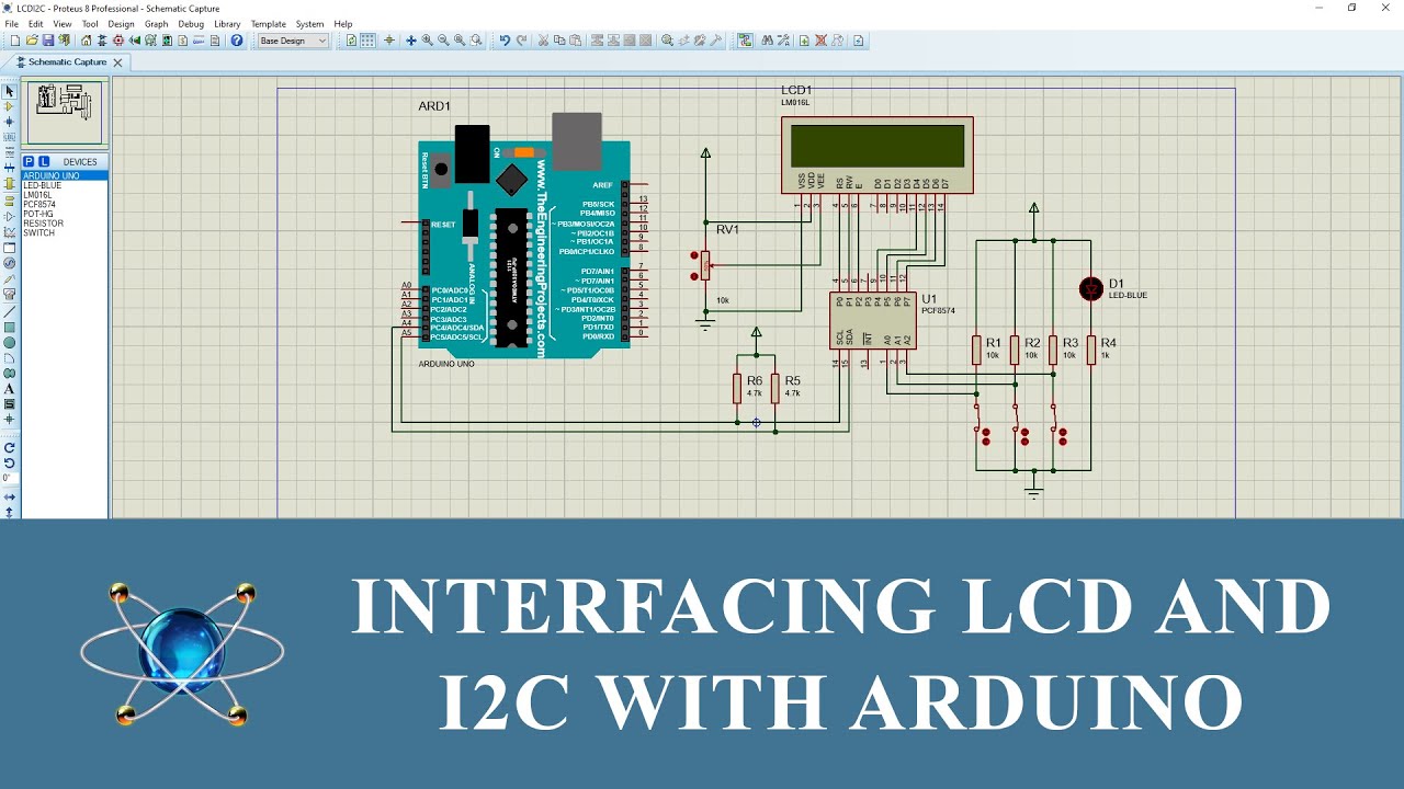
How to Interface and Addressing LCD and I2C with Arduino in Proteus 8
Click CC to select English, Malay, Indonesia, Filipino and Hindi subtitles.Description: This video shows how to interface and addressing LCD and I2C with Ard.

I2c proteus
Arduino with SSD1306 OLED in I2C mode - Proteus simulationCircuit diagram, Arduino code and Proteus simulation files:https://simple-circuit.com/arduino-ssd13.

How to Use LCD in Proteus Arduino LCD 16*4 I2C Proteus Simulation and
Arduino ATMEGA328 EEPROM I2C Simulation in Proteus 8.6 SP1. Below Ardiuno ATMEGA controllers can be simulated in Proteus. LilyPad, LilyPad SimpleSnap, LilyPad USB, Mega 2560, Micro, Pro, Pro Mini,.
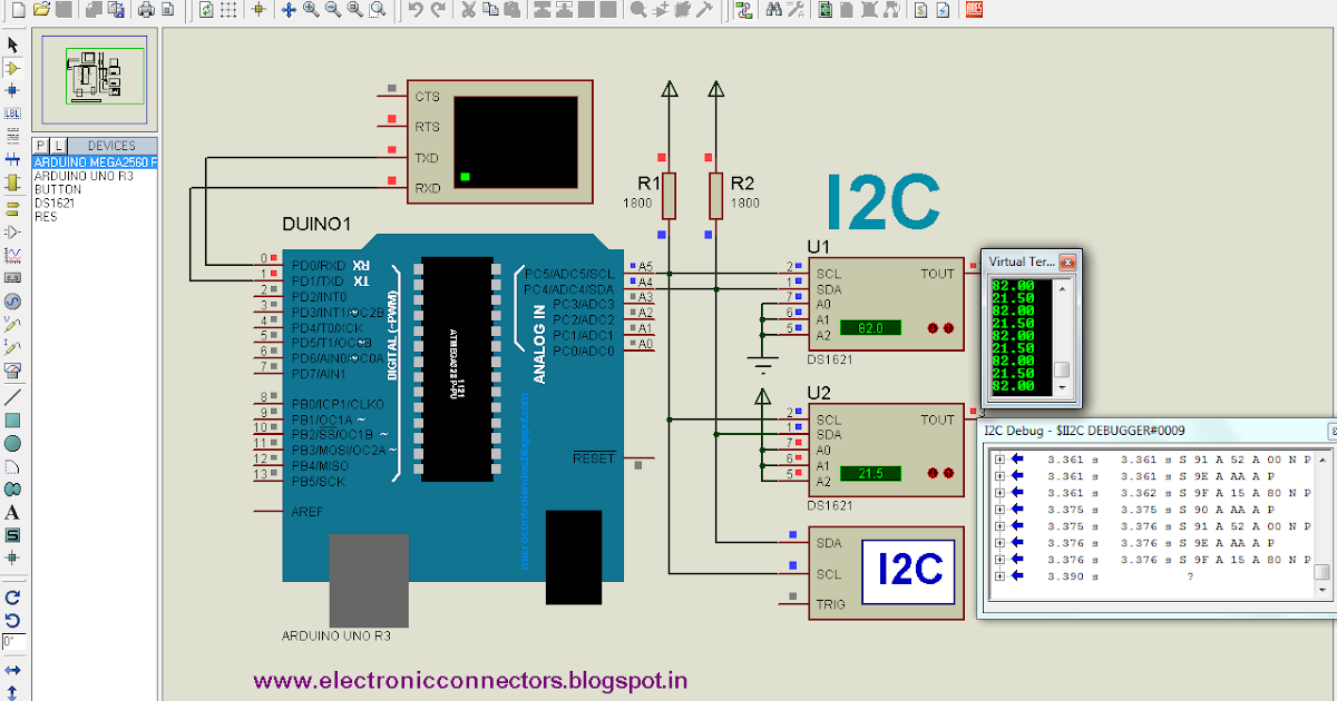
ELECTRONIC CONNECTORS I2C in ARDUINO UNO & PIC Microcontroller with
Simulation of JHD-2X16-I2C I2C LCD 16x2 with Arduino in Proteus.#arduino #proteus #lcd #i2c

Interfacing I2C LCD with Arduino Mega 2560 in Proteus
The RTC - DS1307 and the SSD1306 OLED share the same I2C bus, which minimizes the number of pins required for the setup. The I2C bus has two lines: SDA (serial data) and SCL (serial clock), an addition rest pin is required for the SSD1306 OLED. So with two push buttons we need a total of 5 pins. The two push buttons are used to set our real.

[Tự học proteus] Hướng dẫn mô phỏng LCD 16x2 và LCD 20x4 I2C với
But I noticed a Proteus I2C debugger bug: if you send an entire sequence, there is a bug foresaid. But if you send from I2C debugger in step-by-step mode, you should make at least two steps since the start till the stop before you send a byte. - D0ct0rD. Aug 10, 2020 at 15:55.

SIMULATION FOR I2C T0 LCD 16X2 USING PROTEUS Networking, Protocols
This video shows how to use the Protocol Analyser in Proteus schematic capture software to look at and control devices on the I2C bus of a simple design whil.

I2c Lcd With Arduino Proteus Simulation And Code Proteus Tutorial Images
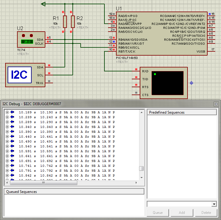
In the above circuit [2], RC4 pin is being used as SDA pin and RC3 pin is the SCK pin.Both of these pins are pulled up using 10K resistors as required for i2c protocol. Proteus provides an 'I2C Debugger Tool' which is attached on the SDA and SCK pins in the above circuit.This i2c debugger tool receives all the i2c messages and displays them on the 'I2C Debug' window displayed in above.

I2c Lcd With Arduino Proteus Simulation And Code Proteus Tutorial Images
Conclusion. In conclusion, mastering the simulation of an I2C LCD module in Proteus with an Arduino Mega 2560 opens doors to efficient and simplified LCD interfacing, significantly reducing the complexity of wiring and I/O pins. This guide, covering the essentials of I2C LCDs, code implementation, and successful simulation in Proteus, empowers.

Arduino with SSD1306 OLED in I2C mode Proteus simulation YouTube
The I2C address of the 8574 on proteus is 0x20. use : LiquidCrystal_I2C lcd(0x20,16,2); for simulation. and LiquidCrystal_I2C lcd(0x3f,16,2); for real hardware. It took me a while to figure it out so am posting here for anyone who might be struggling with the same issue.

Proteus Arduino i2c 20x4 LCD Display Menu Tutorial, Scrolling Menu, Set
Using I2C debugger in Proteus Home. Forums. Education. Homework Help. Using I2C debugger in Proteus. Thread starter Cable Guy; Start date Mar 23, 2012; Search Forums; New Posts; C. Thread Starter. Cable Guy. Joined Mar 23, 2012 3. Mar 23, 2012 #1 I want to simulate communication with an MCP9801 serial output temperature sensor in Proteus VSM by.

I2c Lcd With Arduino Proteus Simulation And Code Proteus Tutorial Images
Abstract. We introduce Proteus virtual development techniques into the microcontroller I2C bus communication designs, and take the AT24C02 for example to explain the Proteus simulation software and hardware design circuit of I2C bus communication. Then we analyse the hardware and software problem in Proteus debugging and provide the solution.

Proteus Arduino i2c 20x4 LCD Display Menu Tutorial, Scrolling Menu
Proteus has a nice instrument called I2C debugger which can be used to read the data on a I2C bus, so let us build a circuit using it and check if the data is being written successfully. The complete circuit diagram is shown below .
First handson with I2C The Answer is 27
The organic diode (OLED) show that we'll use during this tutorial is the SSD1306 model a monocular, .96-inch show with 128×64 pixels. The OLED show doesn't need backlight, which ends up terribly very nice distinction in dark environments. To boot, its pixels absorbs energy only if they're on, that the OLED show absorbs less power contrast.

How to Connect Multiple LCD to Arduino in Proteus Demonstration with
This video is demonstrated Simulation on Proteus of I2C LCD16x2 with Arduino Step by step. #voidloopRobotech #i2cLCD16x2 #vlRobotech #Proteus #Arduino_Simul.
